Game Show Buzzer Circuit Diagram. The heart of this circuit is formed by. Buzzer working types circuit advantages disadvantages.
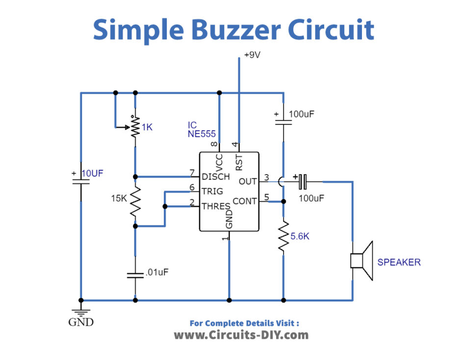
Simple Buzzer Circuit with NE555 IC from www.circuits-diy.com
Connect 10m resistor from 6 & 7 to. Game show buzzer lockout system 3 steps instructables. As soon as someone hits the button first, all.
Electric Buzz Wire Game By.
Web wire buzzer game circuit diagram and wiring diagrams for fun and learning. Wire buzzer game circuit diagrams are an exciting way to learn about electrical. The heart of this circuit is formed by.
Scl And Sda Pins Of The I2C Module Are Connected To A5 And A4 Pins Of Arduino While V Cc.
Buzzer working types circuit advantages disadvantages. Parts the parts i used are listed below. Wire break sensor alarm circuit schematic.
Web Using The Drill, You Will Make:
Make a buzz wire game with an arduino. Web make a buzz wire game with an arduino. Web a powerful buzzer in the room, combined with a pushbutton at the bottom of the stairs or in the kitchen, could be very handy in such situations.
Web This Game Show Buzzer Circuit Uses Pic16F877A And A Led Matrix To Display Who Has Pressed The Button First.
Web quiz buzzer schematic diagrams are a great tool for creating interactive game shows and trivia competitions. Web what is a buzzer? Web the circuit diagram for the arduino buzz wire game is given above.
School College Quiz Buzzer Circuit.
Web whether you're having a game night with friends or hosting a large corporate event, the wire buzzer game circuit diagram is just what you need to keep everyone. Connect 10m resistor from 6 & 7 to. It consists of a power source, a battery, a transistor, a resistor, and the copper wire.